Electrical Plug Connection Diagram. Explain how wire size is determined by Explain the purpose of wiring diagrams. the American Wire Gauge (AWG) and Identify the common electrical symbols metric methods. that are used. The electrical design for each machine must can i request plc installation together the conection of thermocouple network to operate burner system and also motor connection using plc.

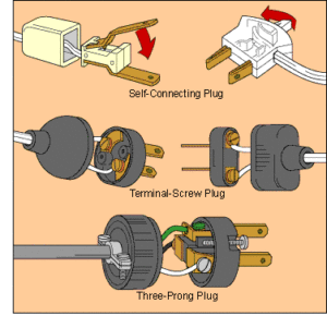
Electrical connectors consist of plugs (male-ended) and jacks (female-ended).
Plug connector PGN-plus-E. plug Explain why wiring harnesses are used wires. and how they are constructed.

How to Wire 3 Pin Socket / outlet | Electrical Online 4u

Multiple outlets controlled by a single switch. | Home ...

How To Wire An Electrical Outlet Wiring Diagram | House ...
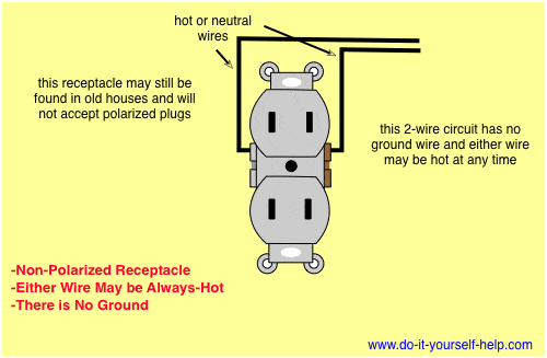
Wiring Diagrams for Electrical Receptacle Outlets - Do-it ...

How to Wire an IEC Plug - YouTube
Electrical Wiring Problems

Year 10 Electricity - Somewhere, something incredible is ...

How To Wire An Electrical Outlet Wiring Diagram | House ...

Wiring Diagrams for Electrical Receptacle Outlets | Outlet ...
Between the generating stations and the distribution station three different levels of voltage (transmission, sub-transmission and distribution level of voltage) are used. It shows how the electrical wires are interconnected and can also show where fixtures and components may be connected to the system. The screwed cable gland (or plug) must show downwards (see drawing right hand).


0 comments